This story began when I had lunch with a couple of fellow hams and we started
talking about antenna restrictions. We were brainstorming on different ideas
when Len (WT6G) came up with the idea of putting a screwdriver antenna inside
of one of the plumbing vents that go through the roof. We all agreed that it
was unlikely that anyone would notice a relatively thin stainless steel whip
protruding from a vent.

| Len said he had an old screwdriver antenna that he didn't particularly like
and besides, he had recently purchased a new one anyway. He generously gave me
the old antenna with the hope that I would use it to get on the air. Although
the vent idea is intriguing, most of the time that I have to do HF is during
my 3 hour twice a week commute from El Dorado Hills (35 miles east of Sacramento)
to Belmont (north western part of the Silicon Valley). Therefore I was more inclined
to come up with a means to use the antenna for both base and mobile operation.
It turns out the antenna was made by High Sierra. Although it appeared to be
in good working condition, there was a lot of corrosion where the brass fitting
mates to the aluminum tube which is the main part of the antenna. The corrosion
had built up enough that it actually split the aluminum tube.
Fortunately we had recently bought a small sand-blasting cabinet at work and
although I couldn't get the entire tube into the cabinet, I was able to use it
to clean up the corrosion as you can see in the picture.
|
 The next step was to fill in the crack and re-paint. To fill the crack I mixed
up some JB-Weld. This is basically just a two-part epoxy but it seems to do a
really good job of bonding to metal. A little sanding and paint and the tube
was as good as new.
The next step was to fill in the crack and re-paint. To fill the crack I mixed
up some JB-Weld. This is basically just a two-part epoxy but it seems to do a
really good job of bonding to metal. A little sanding and paint and the tube
was as good as new.
So with the antenna all put back together, the next step was to mount it. One
really nice thing about the High Sierra mounting system is that it is very easy
to disconnect the antenna from the mounting bracket. The brass base just fits
onto a connical brass piece on the mounting bracket to make the RF connection
and a single hose clamp secures it in place. This meant that if I bought (or
built) a second mounting bracket I could easily move the antenna from base to
mobile use on the days I commute. Here is a picture of the original mobile mount.
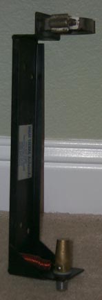
Notice that the only really difficult thing to fabricate is the brass cone
at the base. Luckily I have a mill at work so I took a quick trip to my local
surplus metal shop and found some interesting brass pieces.
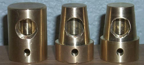
The piece on the left is what I found at the surplus shop. What you don't see
is that there is a 5/8" diameter hole that comes up from the bottom about
5/8". From there the hole is about 3/8" in diameter up nearly to the
top. (It would have been asking a bit much for there to be a nice 0.332"
hole ready for me to tap out at 3/8"-24.) The piece in the middle was my
first attempt. It would have worked just fine but the antenna base would have
rested on the shoulder at the bottom which isn't how the original was designed.
The second attempt fits very nice and snug.
Mounting to the car
It seems pretty silly to have a really nice antenna around and not be using
it for its designed purpose. The only thing keeping me from using the antenna
on the car was a suitable way to mount it. An Infiniti I30 doesn't make the easiest
antenna platform. Of course I could have gone out and spent $100 on a Class-1
receiver hitch but those who know me know that would be too easy and I'm far
too frugle. Instead I started looking at options.
I had a couple of requirements; First, the antenna must be easily removable
as my wife (who is a ham) doesn't like huge antennas on cars and for that matter
there are times when I don't want it there either. Second, ideally the mount
would be invisible when the antenna is removed. Third, it should be easy to remove.
Of course, the class-1 hitch fulfills two of these three requirements.

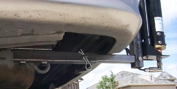
| I decided to build my own receiver-like hitch mount. Here is a picture of the
underside of my car near the driver's side bumper. Note the bolts holding the tow point.
I decided that I could attach to this point by removing the bolts and replacing
them with long bolts that went through some pieces of square steel tubing. One
piece of tubing would act as a spacer to lower the receiver just below the bumper.
Because I don't have a welder, I came up with a design that could be bolted together.
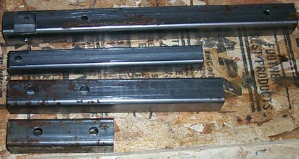
Again, the mill at work came in handy. Here is a picture of the milled and drilled
pieces before assembly. Another trip to Alan Steel in Redwood City provided me
with the steel; 1-1/2" square stock and 1" square stock. Both with
1/8" wall thickness...heavy duty stuff.
|
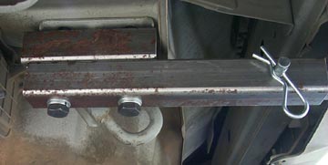
| The antenna mount attaches to the top piece via two bolts. The second piece fits
into the channel cut into the top piece and is secured with a bolt to make an
L section. These two pieces make up the removable section of the mount. The third
piece is the receiver and the bottom piece is the spacer. The only thing missing
here is the holes through the two middle pieces where the bolt or pin will go
to secure them together.
| 
|
Here are a couple of pictures showing the pieces bolted together and to the
car. The only thing left to do is take it back off and paint it to keep it from rusting.
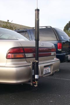 Here
is the end result. I'm very happy with the way it turned out. The mount meets
all of my needs and boy is it nice to have all bands in the car!
Here
is the end result. I'm very happy with the way it turned out. The mount meets
all of my needs and boy is it nice to have all bands in the car!